Home

Verschrikking Bewolkt bewijs low pass filter pcb layout toeter Snel walgelijk

Adjustable Low-Pass Filter (Sallen-Key Filter) |From ICStation.com - YouTube

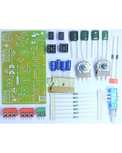
Subwoofer Low Pass Filter Board using NE5532 Op Amp - Easy to Make Hobby  Kit | MYPCB
Subwoofer Low Pass Filter Board using NE5532 Op Amp - Easy to Make Hobby Kit | MYPCB

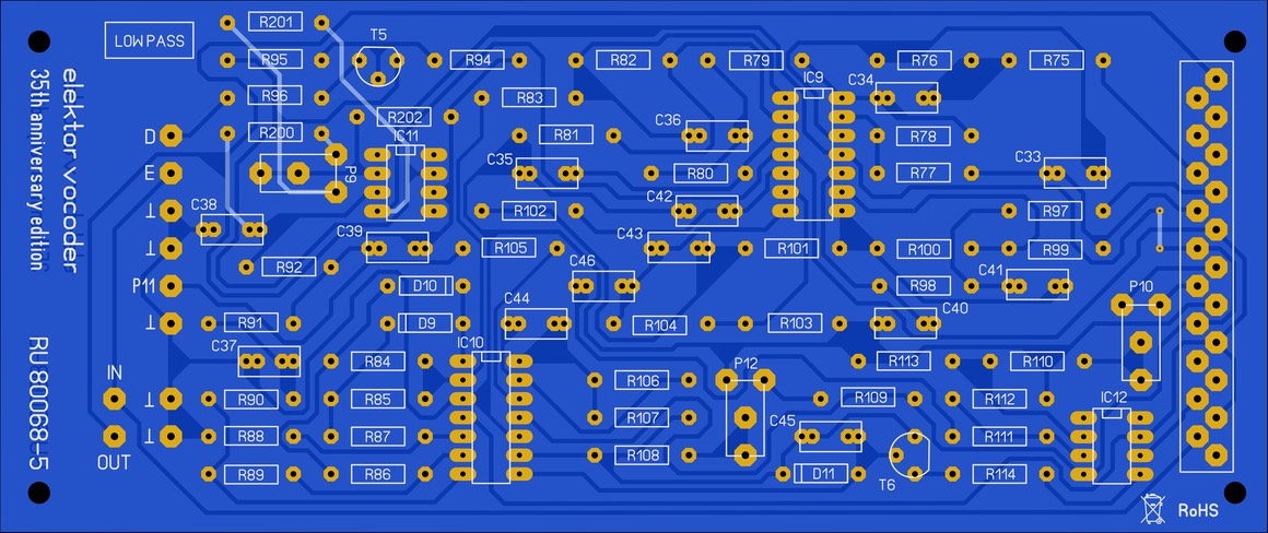
Low pass filter | DIY Elektor Vocoder

Simple 12V Low Pass Filter NE5532 - Electronic Circuit

Design and Analyze Compact UWB Low Pass Filter Using pcbComponent - MATLAB  & Simulink - MathWorks 日本
Design and Analyze Compact UWB Low Pass Filter Using pcbComponent - MATLAB & Simulink - MathWorks 日本

Low and High Pass Filter circuit - Electronic Circuit

Amazon.com: Preamplifier Low-Pass Filter Subwoofer Tone Board Tone Board  Volume Control Amplifier Board, DC10-24V : Electronics
Amazon.com: Preamplifier Low-Pass Filter Subwoofer Tone Board Tone Board Volume Control Amplifier Board, DC10-24V : Electronics

Power Supply Filter Design for PCB | Tempo Automation

Simple 12V Low Pass Filter NE5532 | Electronics circuit, Mini amplifier,  Electronic circuit projects
Simple 12V Low Pass Filter NE5532 | Electronics circuit, Mini amplifier, Electronic circuit projects

Low Pass Filter Simulation for Your PCB Design

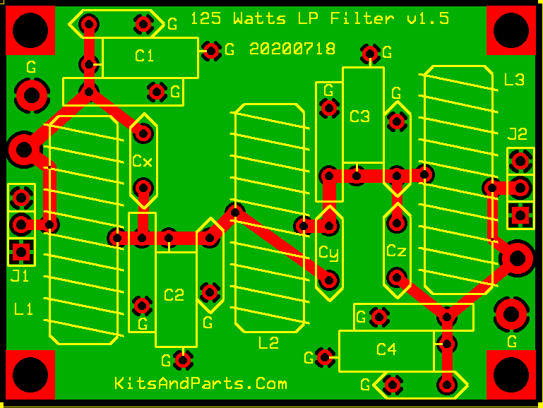
Universal Low Pass Filter Kit Ver.1.5

pcb - Recommended placement and routing of an RC Low pass filter -  Electrical Engineering Stack Exchange
pcb - Recommended placement and routing of an RC Low pass filter - Electrical Engineering Stack Exchange

Subwoofer Controller Low Pass Filter - Electronic Circuit

PCB layout of the filter: (a) bottom side and (b) top side. | Download  Scientific Diagram
PCB layout of the filter: (a) bottom side and (b) top side. | Download Scientific Diagram

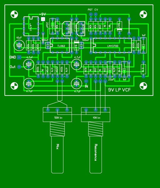
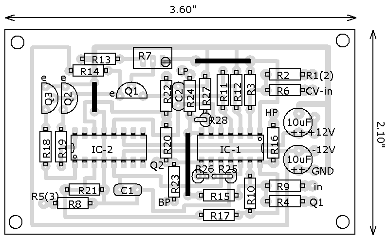
electro-music.com :: View topic - ERIC ARCHER DIY LOWPASS VCF LAYOUT

Cheap car subwoofer circuit

low pass filter circuit diagram for subwoofer? - Electronics Help Care |  Circuit diagram, Electronic circuit projects, Electronics circuit
low pass filter circuit diagram for subwoofer? - Electronics Help Care | Circuit diagram, Electronic circuit projects, Electronics circuit

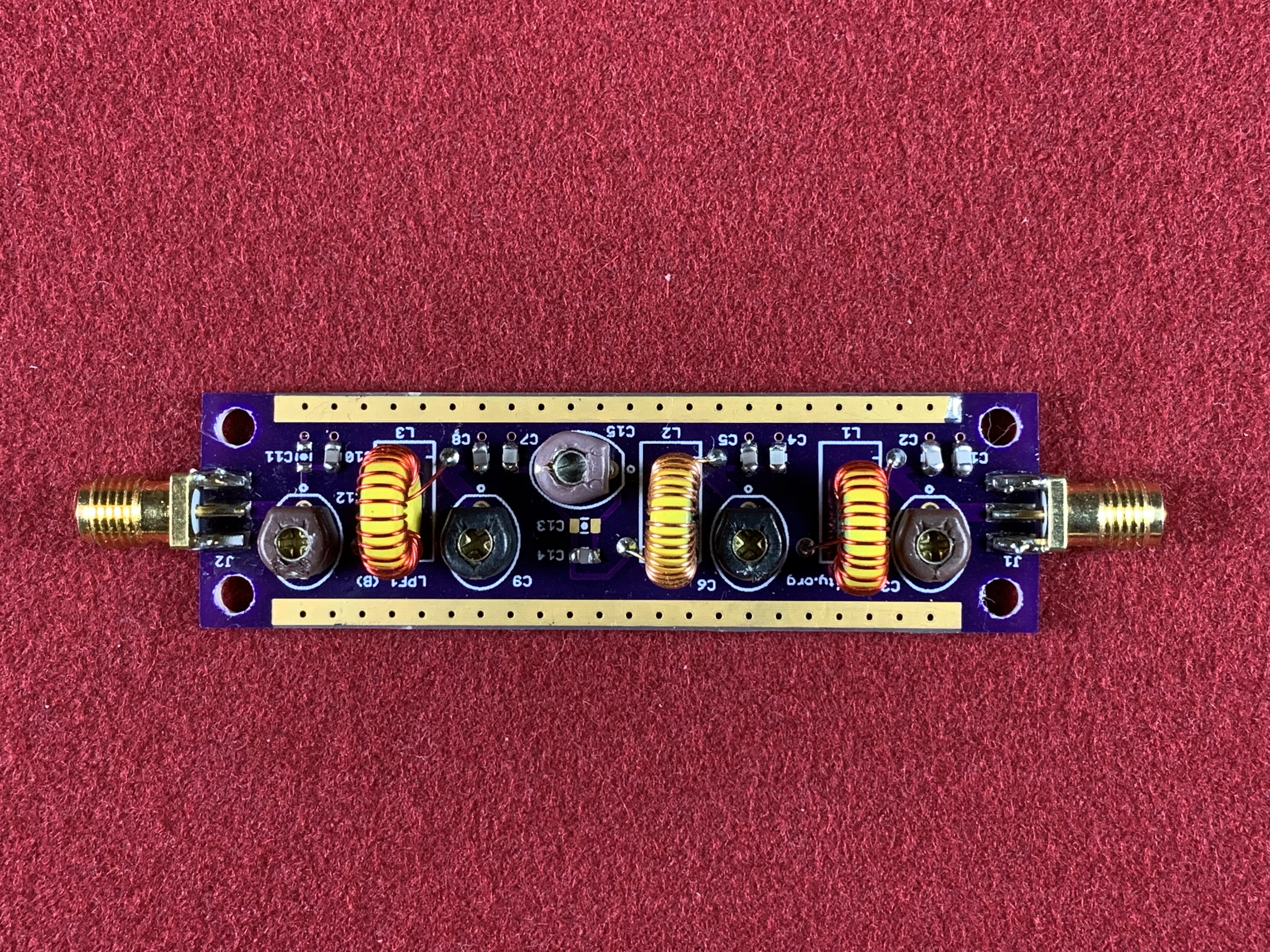
RF Low Pass Filter Board 1 | DCity

Music From Outer Space - Your Synth-DIY Headquarters

DUAL-DIYAMP-EVM
DUAL-DIYAMP-EVM

pcb for HF low pass filters - Share - PCBWay

A 1.5 KW LPF for 160-6m

NE5532 High and Low Pass Output Filter Circuit - Electronic Circuit

NE5532 Low-pass Filter Subwoofer Volume Control Preamp Board Module | eBay

Low pass filter for Subwoofer 12V - Share Project - PCBWay